2) Modeling of Unsaturated Flow through Dual-Scale Porous Fiber Mats in Liquid Composite
4) Flow Modeling in Green Composites
5) Evaporation in Porous Media: Multi-component Liquid Transport
6) Evaporation in Porous Media: Pore Network
8) Calibration of Permeability Evaluation Test Setups
10) Making Next- Generation Scaled CNF Nanocomposites using LCM Technology
1) Designing Next-Generation Water Filters using Advanced Micro-Macro Simulations based on mathematically-rigorous Volume Averaging Method
Today, one of the major health hazards worldwide is contamination of water through various pollutants including heavy metals such as arsenic and lead, which leads to development of different kinds of health problems. To tackle this issue, one of the most common trace-pollutant removal technologies involve the usage of conventional sorbents in the form of porous filters which primarily function on the principle of adsorption of pollutants by the solid phase in particulate form.
Our research group aims to solve this challenging problem by optimizing and improving water filters which house adsorptive-porous cartridges. The overall design of the porous media is optimized through advanced micro-macro flow and transport simulations developed in-house. We investigate the entire spectrum of processes concerned with the development of this product which range from studying the solute transport phenomenon in conjunction with adsorption at the microscale level to fabricating and testing the newly-designed cartridge at the lab scale.
On the theoretical front, the well-respected and mathematically-rigorous volume-averaging method is used to upscale the traditional point-based convection-diffusion equation, which represents the migration of ionic species present in tracer amounts in water, to macroscopic transport equations for predicting arsenic concentrations in the filters. This theoretical model is numerically tested on artificial geometries built in accordance with the complex pore structures found in real-world cartridges. One of the simulation results illustrating the adsorbent consumption in a cartridge model with respect to time (ranging from t = 0 day(s) to t = 300 day(s)) is shown here.
https://sites.uwm.edu/porousmedia/files/2020/09/dilute-conc.gif
The experimental part of the research involves setting up a sophisticated data acquisition network using the industry standard system-design platform, LabVIEW, to monitor and collect the flow data, as well as enable close control over the transducers integrated in the network. Also, we carry out initial tests to adjudge the filtration efficacy of cartridges, such as an experimental one (made in our lab) of polyurethane foam (PU foam) loaded with iron-oxide nanoparticles. Previously, we have fabricated PU foam samples (Fig. (a)) and installed a basic experimental set-up (Fig. (b)), as shown in the figure below:

Further, the optimized pore structures would be converted into 3-D printable files and the end product can be fabricated using 3-D printers. After such manufacturing, the next-generation products would be tested using our experimental set-up and fine-tuned to compete against the market standards. Overall, this interdisciplinary research involves fluid mechanics, mass transport and CFD to formulate the theoretical solute transport model and perform experimental calibration for chemical species measured in the test samples, electronics engineering to set-up the data collection and acquisition platform, and mechanical engineering to fabricate the water filters using the additive manufacturing method of 3-D printing.
2) Modeling of Unsaturated Flow through Dual-Scale Porous Fiber Mats in Liquid Composite
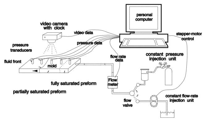
Liquid Composite Molding (LCM) processes, including Resin Transfer Molding (RTM), Vacuum Assisted Resin Transfer Molding (VARTM), and Seemann Composites Resin Infusion Molding Process (SCRIMP), have become important methods for manufacturing polymer composites. One of the main activities of this research group is to investigate the physics of resin flow through a mass of reinforcing fibers in Liquid Composites Molding (LCM) processes used in the manufacturing of polymer composites. The experimental station shown on the main page is currently being used to study the physics of flow of thermosetting resin in a mold packed with reinforcing fibers in the form of woven fiber mats. Schematic of the computer aided data-acquisition and data-processing platform developed in the lab is as follows:
To find out more about the details of this project, please visit here
3) Wicking in Porous Media
Factors affecting the wicking rate are also being studied here in this lab. Factors such as external pressure (hydraulic pressure) and structural changed (swelling or contraction) are under study in our research projects.
Spontaneous Imbibition of Liquid in Glass fiber Wicks
In this first part of our research, a theoretical model for wicking of a liquid into a glass-fiber wick is developed based on the sharp-front or plug-flow assumption with single-phase Darcy flow occurring behind a clearly-defined liquid front. Such an approach is superior to the traditional Washburn equation based approach derived from unidirectional capillary tubes as it allows one to model wicking in 2-D and 3-D geometries. The newness of the formulation lies in the fact that it was developed for wicking along fibers of a transversely-isotropic porous wick made from bundles of parallel glass fibers. The simplification of the permeability tensor for this system leads to a straight-forward development of a formula for the liquid-front height as a function of time. Later, the liquid-front height was shown to be directly obtainable from the mass of the liquid absorbed by the wick as a function of time.

Experimental setup for measuring the mass of liquid spontaneously imbibed by the wick using a sensitive balance
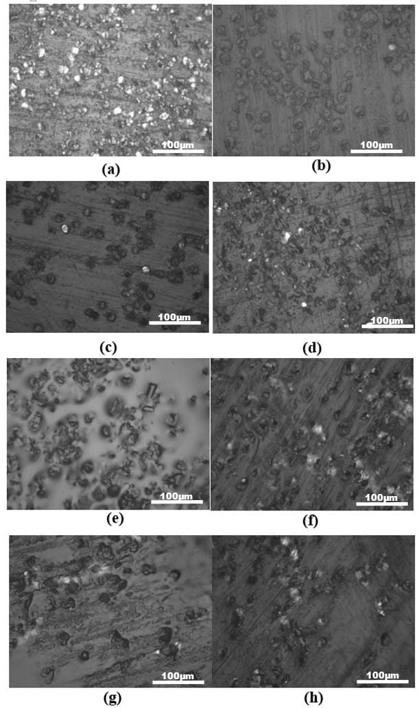
Typical optical micrographs of the cross-sections of wicks samples cast in epoxy for measuring porosity ( . The spotty dark spots represent fiber cross-sections while the lighter background is the epoxy matrix
The proposed theoretical model is tested against the results of a mass-gain experiment designed to study wicking of a liquid in vertical wicks. Eight different glass-fiber wicks, named from A to H, were used with a single wicking liquid (a hydrocarbon based oil) in the experiment. In order to avoid the usage of any fitting parameters, all the parameters involved in the problem were measured independently. They included the properties of the fibrous porous medium [porosity, axial permeability, fiber diameter], properties of the wetting liquid [viscosity, surface tension] and finally, the property related to the interaction between the solid and liquid phases [contact angle]. Estimation of the axial permeability, measured using the falling head permeameter, involved developing a novel formula using the flow formulation for a transversely-isotropic porous medium of the fiber-glass wicks.
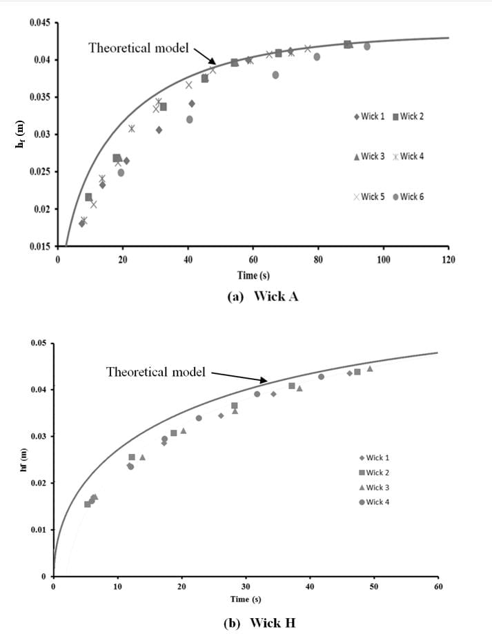
The proposed theoretical model for predicting the height of liquid-front as a function of time during wicking. The model is compared with the experimental data for the wicks A and H.
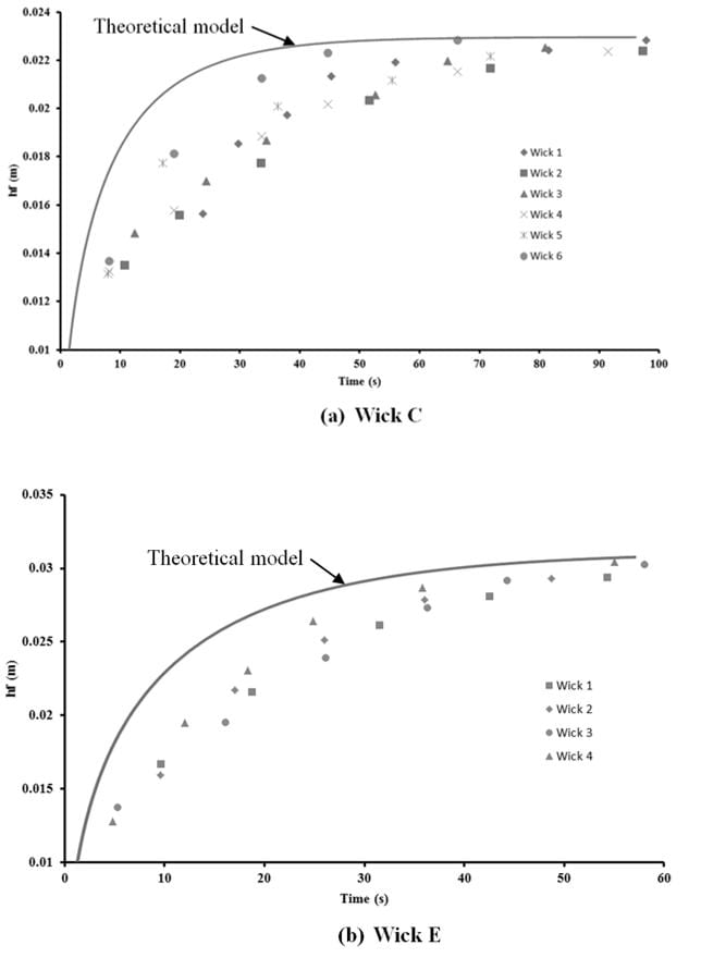
The proposed theoretical model for predicting the height of liquid-front as a function of time during wicking. The model is compared with the experimental data for the wicks C and E.

The proposed theoretical model for predicting the height of liquid-front as a function of time during wicking. The model is compared with the experimental data for the wicks F and G

The proposed theoretical model for predicting the height of liquid-front as a function of time during wicking. The model is compared with the experimental data for wicks D and B.
From the comparison of the experimental results with the theoretical predictions, it was observed that the proposed theoretical model is able to predict wicking most satisfactorily only in wicks A, D and H. For the other remaining wicks (B, C, E, F, G), it is not as effective. The reason for this discrepancy could be traced to the lower contact angles seen in the former wicks that translate into higher capillary suction pressures, and which could possibly help in creating a sharper liquid-front during wicking. The general reasons for the differences between experiments and theory could also be traced to the lack of homogeneity in the wicks due to the clustering of fibers seen in the wick cross-section micrographs. The lack of homogeneity may also cause fudging of the sharp liquid-air interface, thereby necessitating the use of an alternative Richard’s equation type approach to model wicking in the glass-fiber wicks. Despite the observed weaknesses of the proposed theoretical model, it was heartening to note that, even for the cases where the model was not particular successful, it was able to predict the wicked height (or liquid-mass absorbed) for some duration during the wicking experiment and provide a satisfactory upper bound for the experimental observations. Our proposed model is powerful as it clearly and explicitly explains the dependence of liquid rise in wicks to the fluid and porous media properties.
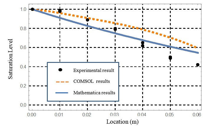
In second part of our research, the Richard’s equation is used to predict liquid saturations inside the glass-fiber wicks made of aligned fibers. In order to find the saturation levels of the liquid in a transversely-isotropic porous medium with a principal direction of the permeability tensor aligned with the flow direction as a function of time and location, we developed and solved an expression based on Richard’s equation. In addition, in order to have a precise comparison between experimental results and numerical outcomes, we solved the Richard’s equation as a partial differential equation numerically in 2-D using COMSOL and analytically in 1-D using Mathematica. All the related properties such as capillary pressure and relative permeability equations as a function of saturation were calculated directly for our particular fibrous porous medium using the state-of-the-art software GeoDict while solving for pore-scale flows within the wick microstructure. The obtained numerical solutions of Richard’s equation were compared with the experimental results which were obtained by measuring saturations (or liquid content) of the wicks at different axial locations.
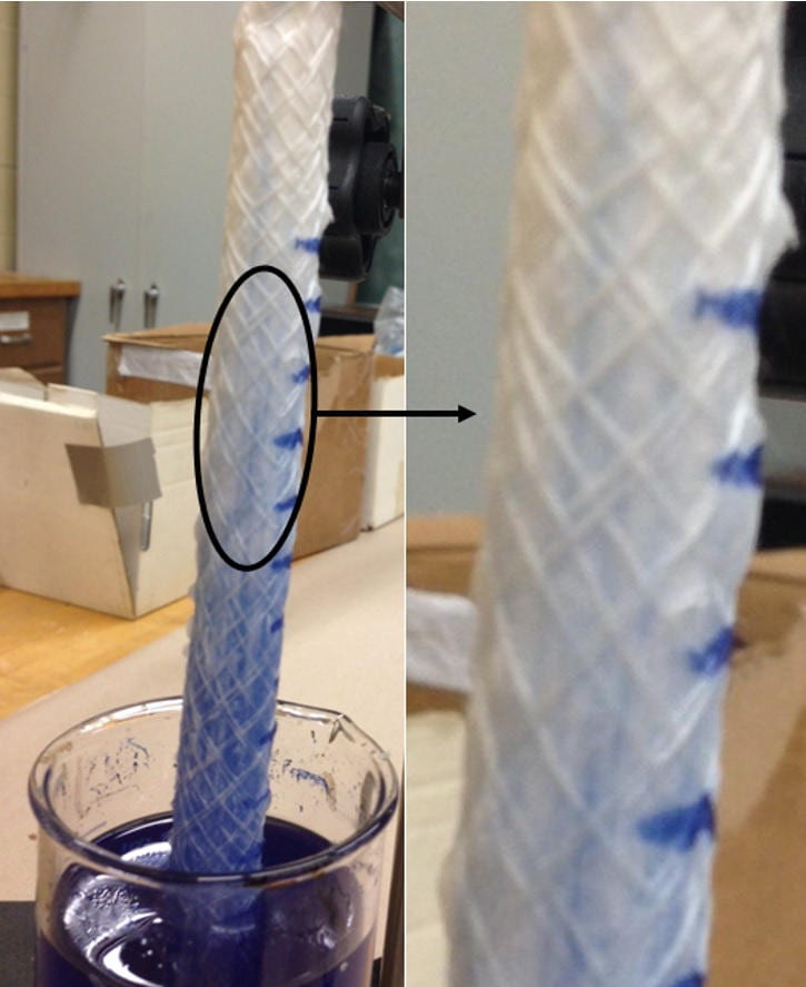
Photograph of a wicking experiment where a glass-fiber wick was dipped in a liquid dyed blue. One can clearly see the saturation gradually dropping from 1 at the wick bottom to 0 at the wick top, thus forming a partially saturated region in the wick above the liquid level. Note the vertical streaks of blue, which indicate the presence of vertical channels for liquids inside the wick.
In our experiments, in order to measure the saturations at different locations, two different types of wicks made of glass fibers, were used. Comparing of the numerical and experimental results indicated that there is a satisfying correlation between the measured saturation levels and the numerical predictions. This good agreement allows us to repose confidence in the saturations predicted using Richard’s equation for unsaturated flows in porous media.
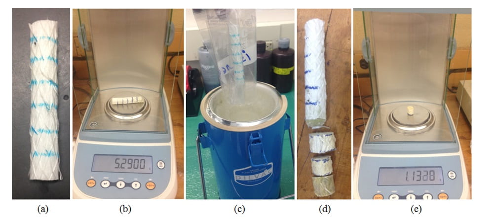
Experimental procedure for measuring saturation distribution along a wick axis
(a) The glass wick is marked wick into equal parts, (b) weighing the dry wick before immersing into the wicking liquid and achieving steady state, (c) submerging the wetted wick into liquid nitrogen to ‘lock’ the liquid, (d) cutting the frozen wick into the marked equal parts, (e) weighing each cut part of the frozen wick
It is clear that there is a reasonable match between the numerical solutions and empirical data.
The numerical solutions of Richard’s equation (obtained after including the gravity effects) in comparison with the experimental data for the first wick
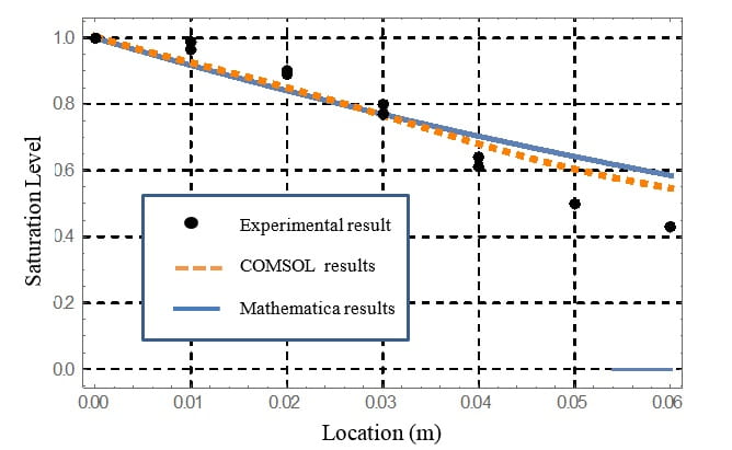
The numerical solutions of Richard’s equation (obtained after including gravity) in comparison with the experimental data for the second wick
4) Flow Modeling in Green Composites
5) Evaporation in Porous Media: Multi-component Liquid Transport
6) Evaporation in Porous Media: Pore Network


7) Ensemble Averaging


8) Calibration of Permeability Evaluation Test Setups
9) Simulation of flow in pressure infiltration of dual-scale 3D woven mats with pure metal in fabrication of Metal Matrix Composites

10) Making Next- Generation Scaled CNF Nanocomposites using LCM Technology
What is CNF?
In recent years, demand for biodegradable, plant-based, composite, also called “green composites” or “biocomposites”, is increasing in various sectors especially the automotive sector of industry. Various kinds of natural fibers have been used in green composites; such reinforcements can be classified into two categories of plant and animal fibers. Plant fibers may be produced from different parts of the plants, such as seed, leave, skin, bast, and fruit. Examples of such fibers are cotton, jute, kenaf, coir, and flax. Examples of animal fibers include silk, sinew, wool, catgut, angora, mohair and alpaca. Natural fibers have lower mechanical properties as compared to carbon and glass fibers. As a result, the current breed of two biocomposites suffers from the twin drawbacks of lower strength and fatigue properties compared with the carbon or glass-fiber based polymer composites.
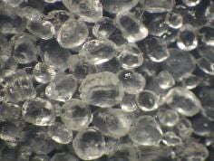
Cellulose nanofibers (CNFs), a new type of nanofibers made purely of cellulose molecules, have very good mechanical property compared to other natural fibers, and even carbon or glass fibers. Recent studies showed that the films or “nanopaper” of CNFs are the strongest man-made, cellulose-based materials. However, the full reinforcing potential of these materials has yet to be realized partly because of issues related to manufacturing processes. Recently, cellulose nanofibers have begun receiving serious consideration as potential reinforcement materials. The big problem with using CNF fibers was the energy requirements for breaking down cellulose fibers in nanofibers were prohibitively high until recently. Recent advances in chemical and mechanical technologies have drastically reduced the energy requirements for producing cellulose nanofibers.
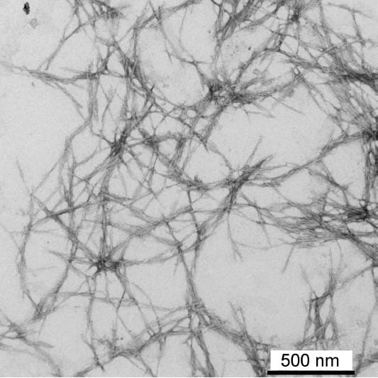

Fig 1. Figure of CNF
Description of LCM Technology for making polymer composites
The liquid composite molding (LCM) processes, including RTM, VARTM and SCRIMP, form an important class of environment-friendly technologies for manufacturing the polymer composites, well known for their light weight, strength and toughness. In LCMs, a resin undergoing the thermosetting reaction is injected into a hollow mold cavity packed with reinforcing carbon or glass fibers. Mold-filling simulations are important approach to optimize the placement of processing parameters to ensure its complete filling. Most of these simulations treat the resin flow as the flow of a liquid through a porous medium where it is assumed that the medium is fully saturated behind the resin flow front in an LCM mold. Recently, researchers discovered that this assumption of full saturation is incorrect for a majority of cases where the reinforcement is in the form of woven, stitched or braided mats made from fiber tows (these fiber mats are often referred to as dual-scale porous media due to the presence of two length scales of pore size in such a porous medium). A distinct region of partial saturation was discovered behind the front where the flow can be characterized as unsaturated flow as shown in the picture. It was discovered that the presence of such a region altered the flow so significantly that it could not be predicted by the typical physics used for LCM simulations.

Fig 2. The experimental setup
Current Efforts to make CNF performes using Freeze- Drying Process
For extra information about current efforts in making CNF perform please visit here.
Current efforts to make scaled CNF nanocomposite using LCM
Cellulose nanofibers are one class of natural fibers that have resulted in structures with remarkable mechanical properties. In this study, the cellulose nanofibers are used as reinforcements in the forms of layered films in a bio-derived resin. Assessment of the tension and fracture behavior is performed for each sample. Crack resistance behavior is compared to glass fiber systems and strategies for improving the fracture toughness of CNF composites are discussed. A bio-based epoxy is used to reinforce the CNF/Epoxy specimens. The epoxy used in all these experiments is a Super Sap 100/1000 made by Entropy Bio-Resins Co. The bio-based 160 epoxy is an epoxy resin that is made from 37% bio-content obtained as co-products of other green industries including wood pulp and bio-fuels production. The resin is classified as a USDA (United States Department of Agriculture) Bio Preferred SM Product using ASTM D6866. The resin has a total calculated biomass of 50%. Using the cellulose nanofiber films as reinforcements, the reinforcements were integrated into the composites.
The testing performed in this section consisted of tension and fracture specimens based on standard specimen geometries. The standards do not directly address nano-cellulose composites, so the specimens were adapted accordingly as noted. The fracture specimens were as described in ASTM D5528 with the following differences. Two sets of specimens are examined; in one case Fibreglast E-glass (Saertex) are used as reinforcements. The glass fibers are primarily in unidirectional form and had a dry areal weight of 955 g/m2. The resin pass through the reinforcement and comes out from two upper connections and goes to resin trap. The samples are ready after one day curring process in room temperature. The pictures of set-up and mold are as follow:

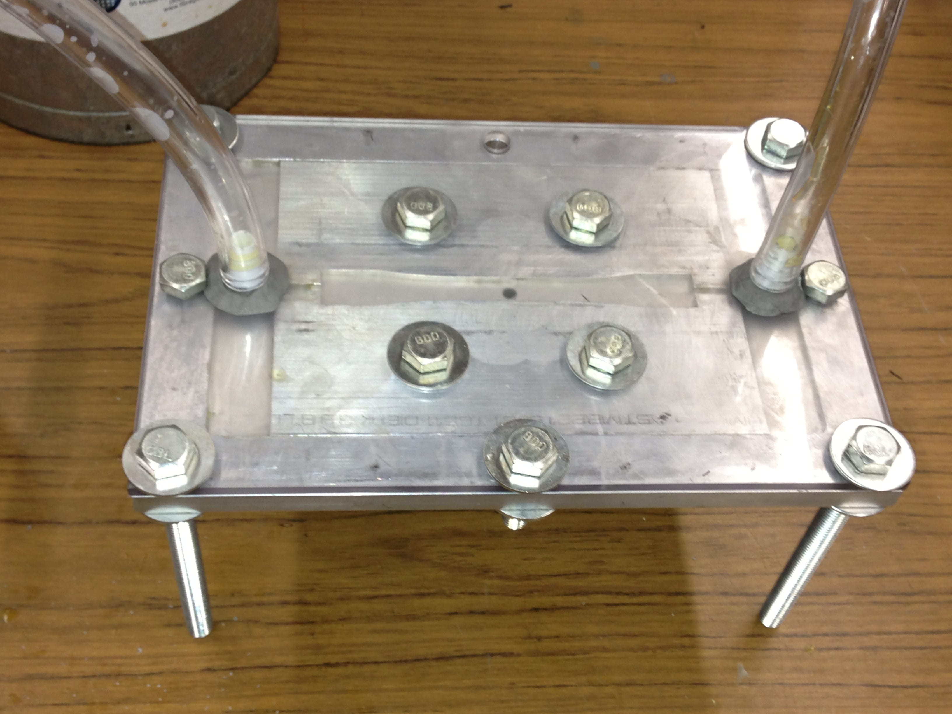
Fig 4. Figures of the mold and experimental setup
For extra information about testing of CNF composites please visit here.
Latest development in making CNF
We are making composite parts that qualify as ASTM standard tensile test specimens. Our goal is to study the resin flow and ultimately the added tensile and flexural strength when using freeze dried, foam, cellulose nano fibers as reinforcement material for Super Sap Resin. These materials are expected to be an important advancement in bio based technology throughout the automotive and packing industries. Our LCM process is based on a conventional injection molding operation. Instead of using positive pressure to inject resin, we use negative vacuum pressure at one atmosphere to pull the resin through the fibers. We have designed our mold using aluminum and polycarbonate because these materials are easily machinable. The mold consists of a base slab of aluminum with removable inserts for tensile and flexurual test samples. A polycarbonate sheet is used completes the air seal and acts as a window to view resin movement. The mold was originally designed for the resin inlet to be in the center of the specimen and the outlets were at both longitudinal ends of the specimen. We’ve found that using this technique creates race tracking down the center of the part because the resin tends to flow around the outer edges of the fibers. This happens because the fiber foam mat is manufactured in such a way that the upper and lower faces of the material have very low porosity and thus low permeability from top to bottom. For better resin flow we inject the resin from one side face and allow it to travel horizontally through the fibers. By using this technique we achieved better surface finish and wetting. The CNF fibers are very light weight and only allow for us to create samples with approximately one percent volume fraction. Using a higher volume fraction stressed our vacuum pump because when the fibers are packed tightly their permeability decreases substantially. This makes it difficult to compare the added strength of the CNF fibers to that of fiberglass of carbon fiber matting because alternate materials such as these have a much higher density. Currently, we are testing our samples for tensile strength. The resin we are using creates issues with an industrial sized tensile testing device because the infusion based resin has a very low viscosity making it very brittle when cured. We have found that conventional testing devices can easily crack the samples when clamped and causes fractures at the grip locations rather than the gauge area.
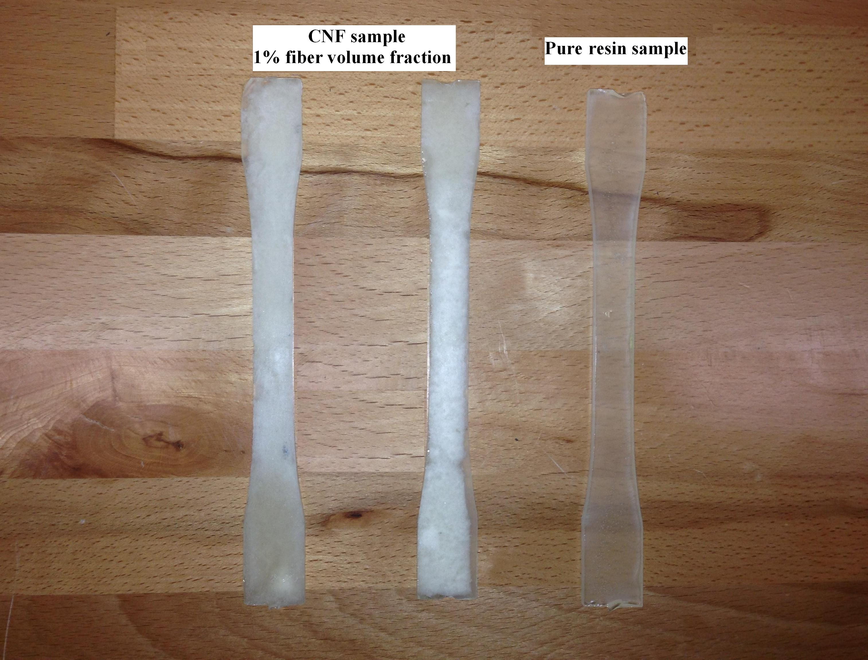

Fig 6. Figure of the CNF sample in Tensile test Machine
To see the resin filling process watch the movie as follow video.
Recent publications in CNF nanocomposite using LCM
1- “Characterization and Processing of Nanocellulose Thermosetting Composites” Ronald C. Sabo, Rani F. El-Hajjar, Craig M. Clemons, Krishna M. Pillai, Handbook of Polymer Nanocomposites. Processing, Performance and Application – Volume C: Polymer Nanocomposites of Cellulose Nanoparticles, Springer-Verlag Berlin Heidelberg 2015; pp. 265-295. (pdf)
2- “Mechanical characterization of cellulose nanofiber and bio-derived epoxy composite” R. Masoodi, R.E. Hajjar, K.M. Pillai, and R. Sabo, Materials and Design, v 36, p 570-576, April 2012. Abstract
3- “An experimental estimation of Liquid Absorption Coefficient for Cellulose Nano-Fiber Films” A. Javadi, K.M. Pillai and R. Sabo, Proceedings of 11th International Conference on Flow Processes in Composite Materials (FPCM11), Auckland, New Zealand, July 9-12, 2012. Abstract
4- “An Experimental Study on Swelling of Cellulose Nano-Fiber Films in Epoxy Resins and Water” R. Masoodi, R. Javadi, K.M. Pillai, R. Sabo, 2011 Spring SAMPE Technical Conference and Exhibition State of the Industry: Advanced Materials, Applications, and Processing Technology, International SAMPE Technical Conference, 2011. Abstract
5- “An Experimental Study on Crack Propagation in Green Composites made from Cellulose Nanofibers and Epoxy” R. Masoodi, R.E. El-Hajjar, K.M. Pillai, A. Javadi, and R. Sabo, 2011 Spring SAMPE Technical Conference and Exhibition State of the Industry: Advanced Materials, Applications, and Processing Technology, International SAMPE Technical Conference, 2011. Abstract
6- “An Experimental Study on Mechanical Properties of Green Composites Made Using Cellulose Nanofiber Films” R. Masoodi, Benton J. Weibel, K.M. Pillai, R.E. Hajjar, and R. Sabo, 2011 ASME International Mechanical Engineering Congress and Exposition, Denver, Colorado, November 11-17, 2011.
7- “Single-Phase Flows in Swelling, Liquid-Absorbing Porous Media:A Derivation of Governing Equations using the Volume Averaging Method” K.M. Pillai, January 8, 2013. Abstract
11) Combustion Simulation
Our research in combustion has been started with the simulation flame over a glass fiber wick of a burning lamp. The first stage of our research started with the characterization of wick and fuel properties such as; porosity, permeability, contact angle, surface tension, etc. Then, we started doing several measurements such as fuel mass consumption and flame length based on combustion experiments. In the next stage based on the experiment, the combustion over the glass fiber wick like the lamp, dove, etc. has been investigated. At this stage, fluid flow and heat transfer studies were included. All the coupled physical problem was solved using CFD analysis. The effect of turbulence on the combustion, characteristic of flow and radiation models were analyzed. Also for the next step, the flow coupled with the combustion inside the wick will be investigated.
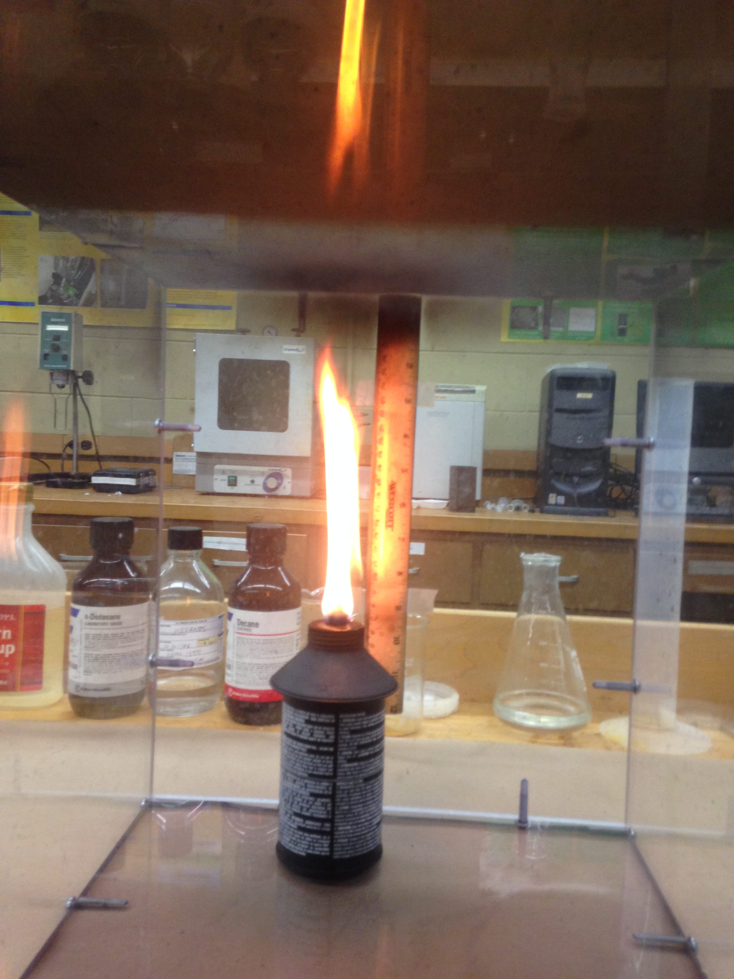
Initial experiments in order to measure the flame length
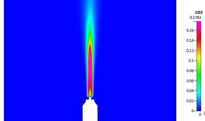
CO2 concentration inside the flame

H2O concentration inside the flame

O2 concentration inside the flame
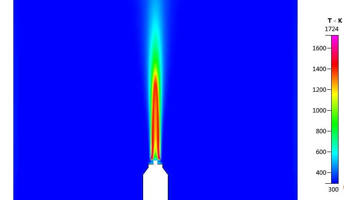
Temperature distribution inside the flame over the wick