|
To investigate the feasibility of the EFT method of testing, a linear elastic SDOF system was tested in the laboratory at the University of Minnesota. A mass-spring-damper system was used for this experimental implementation. A cart served as the mass and a high-strength rod with an initial pretension of 15 kips (to prevent bar from buckling) served as the spring. Effective forces were applied to the lumped mass (cart) using a 77 kip hydraulic actuator. A three-stage servovalve with 90gpm flow rate was used to control the actuator. The feasibility of the EFT method was investigated by comparing the input effective force function (command signal) with the force measured by the actuator load cell.
|
|
|
The properties of the system were investigated through a series of free and forced sinusoidal vibrations and static loading tests.
- Weight = 17.5 kips
- Stiffness = 67.1kips/in.
- Damping ratio = 0.02
- Natural frequency = 6.1 Hz.
|
| Simulation Models: |
 Top Top
|
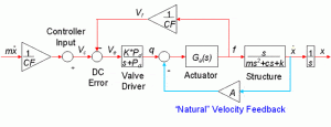
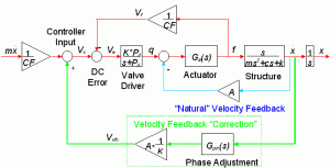
Simulations of the actuator/control/structure interaction were conducted using SIMULINK, a tool box in MATLAB. The simulations provided the investigators with the necessary insight to overcome the “natural” velocity feedback problem which inhibited the direct implementation of the EFT method. The simulation also helps the power capacity check.
|
|
|
|
The “natural” velocity feedback problem arises because the actuator is unable to apply force to the test structure at the natural frequency of the structural system due to the interaction between the actuator and the structure
|
|
|
|
Using the measured velocity of the structural system, the increased flow to the actuator required to overcome the velocity feedback phenomenon can be incorporated in the control loop.
|
| Selected Results: |
 Top Top
|
  |
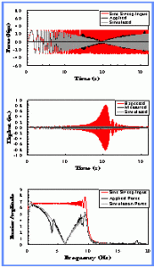
The left graph shows no energy input at natural frequency of structural system due to velocity feedback loop.
While on the right, measured forces match command forces well.
However, there is indication of nonlinearity in flow-velocity relationship not accounted for in simplified linearized velocity feedback correction (attributed to pretension in spring)
|
 |
 |
Similarly, in the direct implementation of EFT, energy input at natural frequency of structural system is limited due to natural velocity feedback phenomenon
After velocity feedback correction being added, energy can be input at the natural frequency of structural systems.
|
 |
Note: lines in red=input or Peff, in black=applied or measured result, in gray=simulation result
| Stage Conclusions: |
 Top Top
|
-
The effective force testing (EFT) method complements existing experimental seismic simulation techniques.
-
“Natural” velocity feedback interaction between the actuator and the structural system inhibits direct implementation of EFT. This limitation may be overcome by employing a “velocity feedback correction” in the control loop.
-
The velocity feedback correction is employed using the measured velocity of the structural system and a phase lead circuit.
|
| Unresolved Issues: |
 Top Top
|
- Natural frequency is around 6 Hz, not close to that of a typical building structure
- There is a unknown mode of motion @ 4 Hz
- The pretension (15 kips) causes initial offset in actuator, which in turn affects the performance of the servo-hydraulic system
- The response is sensitive to the magnitude and phase adjustment of the velocity feedback compensation
In addition,
- Actuators may affect the system response by adding mass or damping
- The repeatability of proposed method needs to be tested
- The performance of EFT method in a nonlinear system should be studied
The current research is aimed at the above issues. |
|Home|Pilot study|Development|Validation|References|Site map|Contact us|


